


Cladding Substructure
☰ Minaret Engineering Menu · Cladding
Minaret Cladding Substructure: Rails, Brackets, Tolerances and Drainage
Specialist MosqueBuild technical guidance for cladding substructure, integrated into the Minaret Engineering Library.
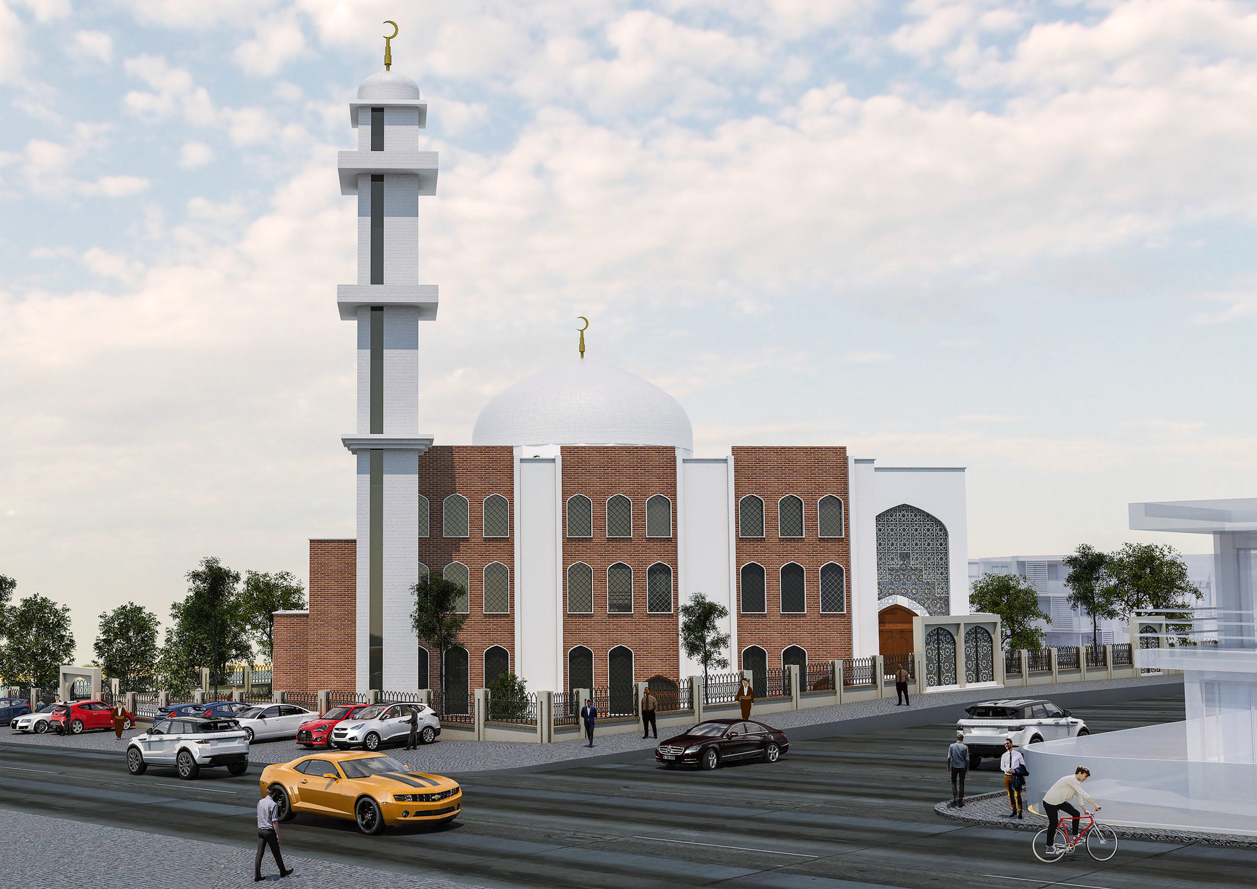
The substructure is the hidden geometry behind the finished minaret
GRP, GRC, metal and stone cladding all depend on a reliable secondary support system. The substructure bridges between the primary tower and the architectural panels, creating fixing points, alignment tolerance and sometimes a drained or ventilated cavity. Because it is concealed after completion, mistakes are expensive to inspect and repair. The secondary frame should therefore be designed as an engineered package rather than left to installers to fabricate from whatever profiles are available on site.
Primary versus secondary steel
The primary structure resists global wind and seismic actions. Secondary rails support panels and transfer local pressure or suction back to the primary members. Confusing these roles can lead to undersized rails or, conversely, unnecessarily heavy cladding frames. Drawings should identify support spans, bracket forces and permitted deflection so the cladding supplier knows what movement to expect.
Rail orientation
Vertical rails are common for panelized systems because they support vertical joint lines and allow water to drain downward. Horizontal rails may be useful at ring joints and decorative bands but can create water traps if their upper surfaces are not drained. Box sections, angles and channels each have different stiffness and coating access. Closed shapes can simplify appearance but need venting and drainage if galvanized.
Adjustable brackets and erection tolerance
A tall steel or concrete shaft will have normal dimensional variation. Adjustable brackets can move the final cladding surface into the architectural line without forcing panels. Slotted holes, shims or threaded adjusters may be used depending on loads and corrosion strategy. Adjustment range should be based on realistic survey tolerances. Excessive stand-off distances increase bracket bending and may require stronger members.
Deflection compatibility
The substructure must be stiff enough for the chosen panel. Flexible GRP may tolerate more support movement than brittle stone or GRC, but excessive rail deflection can still open joints and fatigue fasteners. Serviceability limits should be coordinated between structural engineer and cladding designer. Supporting a rigid panel on a flexible rail often creates cracking even when neither component fails in a simple strength check.
Thermal movement
Aluminium, steel, GRP and metal cladding expand at different rates. Secondary frames need fixed and sliding points where long runs could otherwise lock movement into panels. A rail spanning several structural modules should not inadvertently prevent the main tower splice from moving as designed. Movement joints in the cladding should align with movement capability in the substructure.
Corrosion protection
Galvanized or coated carbon steel is common for secondary framing. The exposure inside a cavity can be severe because moisture may enter while drying is slow. Protection should match the actual microclimate, not only the exterior appearance. Cut edges and site welds need repair. Stainless or aluminium brackets may be appropriate in some systems but require galvanic compatibility review.
Dissimilar materials
Copper or brass cladding should not drain directly onto incompatible steel or aluminium without analysis. Stainless fasteners through aluminium rails and galvanized steel can also create local galvanic cells in wet conditions. Isolation tapes, polymer pads and compatible washers help separate materials while still transferring load. These details need to survive compression and UV exposure where they are not fully concealed.
Drainage and ventilation
If water passes through outer joints, the cavity should direct it toward exits rather than trapping it at brackets. Rails should be arranged so drainage paths remain continuous. Ventilation openings may reduce condensation and speed drying, particularly behind metal skins. Openings need insect screens or baffles where appropriate. Fire-stopping requirements may also affect cavity continuity and must be coordinated with local regulations.
Penetrations and equipment
Speaker brackets and lighting should attach to dedicated structural points, not random cladding rails unless those rails are designed for the extra load. Cable penetrations should use sleeves and glands. Planning these zones in the substructure prevents installers from drilling through finished panels and compromising water management.
Panel replacement strategy
A substructure should make individual panels replaceable wherever practical. Hidden clips may improve appearance but need a known release sequence. Mechanical fasteners should remain reachable from planned access points. If a damaged panel requires cutting rails or dismantling an entire balcony, the original support concept has created a life-cycle problem. Replacement paths should be considered during shop drawing review.
Survey and handover
Before cladding starts, the primary shaft should be surveyed and rail alignment checked. Key dimensions can be recorded in an as-built model or drawing. The handover package should identify rail material, coating, bracket type, fixing torque where relevant and any areas requiring access. A good cladding substructure disappears visually but remains traceable technically, providing the alignment, drainage and load transfer that make the outer minaret skin reliable.
Explore Mosque Minaret Systems
Continue from this guide to the main solution page, technical directory and closely related resources.
 English
 German
 Turkish
 Russian
 French
 Arabic