

Teknik dokümantasyon
Chandelier Shop Drawing & Technical Submittal Guide
For large custom chandeliers, drawings are the bridge between design intent and fabrication. A useful shop drawing package should allow the architect, MEP team, structural team and installer to understand exactly how the fixture fits the building.
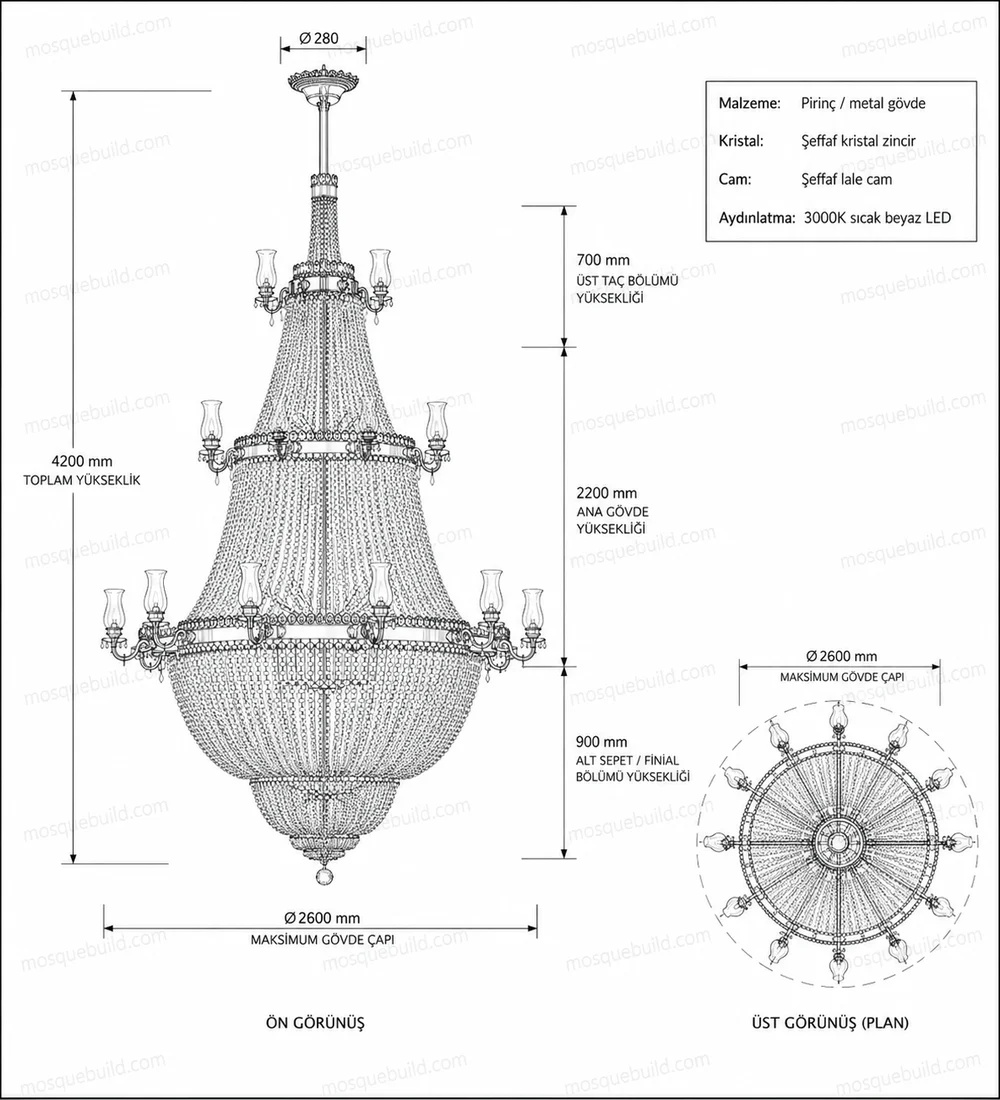
What a chandelier shop drawing should show
Toplam Ölçüler
Plan width/diameter, total fixture height, suspension length and lowest finished elevation.
Askı noktaları
Number, spacing and location of support points, plus canopy or ceiling interface geometry.
Modül Dağılımı
Large fixtures should identify transportable modules, assembly joints and installation sequence.
Elektrik yerleşim planı
Circuits, drivers, lamp/LED zones, cable routes and control interfaces should be coordinated with the MEP package.
Yararlı çizim seti
- Genel yerleşim planı
- Ön ve yan görünüşler
- Armatür kesiti
- Rozans ve askı detayı
- Structural load information provided for coordination
- Elektrik ve sürücü yerleşimi
- Module and assembly identification
- Yüzey bitişi ve malzeme çizelgesi
- Montaj notları
Coordination with architectural and MEP drawings
The chandelier drawing should be checked against the reflected ceiling plan, structural ceiling support, sprinkler/fire systems, HVAC diffusers, speakers, access panels and other services. For atriums and ballrooms, this coordination is especially important because decorative lighting occupies a large ceiling zone.
Need a technical submittal package?
Send the approved architectural drawings, ceiling information and selected chandelier direction to define the required drawing scope.
İmalat çizimi koordinasyonu talep etOnay ve revizyon kontrolü
A chandelier shop drawing is useful only when its revision and responsibility are clear. The submission should identify the project, fixture code, drawing number, revision, issue status and the exact architectural/structural references used for coordination.
- Confirm overall diameter, fixture height, suspension drop and finished lowest elevation.
- Show every structural suspension point and the load information needed by the responsible structural engineer.
- Identify electrical circuits, drivers, dimming/control zones and accessible maintenance locations.
- Show transport modules, assembly joints and site connection details for large fixtures.
- Record approved metal finish, glass/crystal type and visible sample references.
- Freeze the drawing before fabrication and track later changes through a formal revision rather than workshop verbal instructions.
For international projects, keep the approved shop drawing linked to packing numbers and installation instructions so site teams can match each module to the current drawing revision.




 English
 German
 Turkish
 Russian
 French
 Arabic